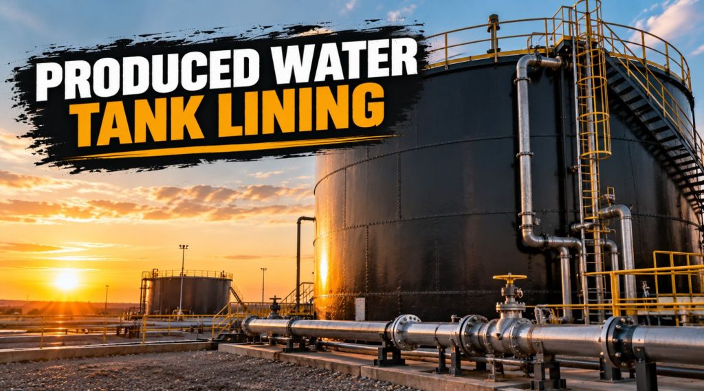
produced water tank lining

Produced Water Tank Lining: Protection for Chloride and H2S Service

Produced water is some of the most aggressive liquid a storage tank ever has to hold, and it rarely shows mercy to whatever lining is protecting the steel underneath. It comes up alongside oil and gas carrying high chloride concentrations, often dissolved CO2, and frequently hydrogen sulfide, and that combination doesn’t just add up to ordinary corrosion risk. It compounds into something meaningfully worse than any single factor on its own. Produced water tank lining has to be chosen with that compounding effect in mind, not just rated against chloride or H2S in isolation, because a lining that handles one reasonably well can still fail fast when both show up in the same tank at the same time.

Why Produced Water Tank Lining Needs to Handle Chloride and H2S Together

Chloride-rich brine attacks carbon steel through pitting and crevice corrosion, concentrating damage at specific weak points, particularly welds, rather than spreading evenly across a surface. That localized attack is part of what makes chloride corrosion so dangerous: a tank can look structurally sound on a visual inspection while a pit is quietly working its way through the wall thickness at one specific spot.

Hydrogen sulfide brings an entirely different failure mode into the picture. In susceptible steels, H2S drives sulfide stress cracking, a brittle fracture mechanism that can develop and propagate far faster than general corrosion, particularly in high-strength steel or in areas with residual stress from welding or fabrication. H2S service also means gas permeation is a real concern for any polymer lining, since dissolved H2S can work its way into a lining’s molecular structure over time, and a sudden pressure drop, during a tank blowdown or rapid depressurization event, can cause that absorbed gas to expand explosively within the lining itself, a failure mode known as rapid gas decompression, or RGD.

Put chloride and H2S together, and add the microbial activity that’s common in produced water tanks, sulfate-reducing bacteria that both generate additional H2S and contribute to localized under-deposit corrosion, and you get an environment that demands a lining genuinely engineered for sour, saline service, not a general-purpose corrosion coating pressed into a job it wasn’t built for.

What This Means for Lining Selection

A lining suited for produced water service needs to do several things simultaneously: resist chloride-driven pitting and crevice attack at the steel interface, maintain chemical stability under sustained H2S exposure without degrading or losing adhesion, and resist gas permeation well enough to avoid blistering under the pressure cycling a produced water tank commonly experiences during normal operation.

Material qualification for sour service isn’t just a performance preference, it’s governed by industry standards, most notably NACE MR0175 and its international counterpart ISO 15156, which set requirements for materials used in H2S-containing environments in oil and gas production. Any lining specified for a produced water tank in sour service should have documented compliance with the relevant sections of that standard for the specific service conditions involved, confirmed against the manufacturer’s technical documentation rather than assumed from general marketing claims about chemical resistance.

Comparing Lining and Tank Options

FactorBare Carbon SteelFiberglass Reinforced Plastic (FRP)Epoxy Phenolic LiningSpray-Applied Polyurea/Polyurethane Lining
Chloride pitting resistancePoorGoodGood when properly appliedGood when formulated for the service
H2S/sour service suitabilityPoor, susceptible to SSCGenerally goodVaries by formulationVaries, must be confirmed against NACE MR0175/ISO 15156
Gas permeation / RGD resistanceNot applicableModerate to goodModerateDepends heavily on specific formulation
Application speedNot applicableSlower, often shop-fabricatedModerate, multiple coats and cure timeFast, seconds to a few hours cure
RepairabilityNot applicableMore difficult, specialized repairModerateGenerally easier, can often be patched in place
Typical costLow material cost, high corrosion riskHigher, especially for new tank constructionModerateModerate, varies by formulation and film thickness

None of these options is automatically correct for every produced water application. FRP tanks offer strong inherent chemical resistance but represent a bigger commitment, usually chosen at the point of new tank construction rather than as a retrofit lining for an existing steel tank. Epoxy phenolic systems have a long track record in oil and gas service and handle a wide range of chemical exposure well, though application and cure time are longer than a spray-applied system. Polyurea and polyurethane linings offer fast application and strong mechanical properties, but sour service suitability varies significantly by specific formulation, making that NACE MR0175/ISO 15156 qualification check a non-negotiable step rather than an assumption.

Where Tank Lining Fits Into the Broader Facility Picture

A produced water tank doesn’t operate in isolation. It’s typically part of a larger tank battery or facility that includes other storage and containment systems facing related, though not identical, exposure challenges. Our guide on tank farm coating maintenance covers the inspection cycle and recoat planning discipline that applies to produced water tanks just as much as it does to crude storage, since both need a program built around actual condition and corrosion rate data rather than a fixed calendar interval. And since produced water tanks sit within facilities that also have to meet secondary containment requirements, our piece on well pad containment systems covers the containment side of that same facility picture, spray-applied, panel, and liner approaches that protect the ground around the tank even as the tank lining itself protects what’s inside it.

Broader corrosion management also matters here. Our pipeline corrosion prevention guide covers corrosion control principles that extend well beyond pipelines into tank and vessel protection generally, and a lot of the same root-cause thinking, surface prep quality, coating selection matched to actual exposure, and ongoing inspection discipline, applies directly to getting produced water tank lining right.

Things to Consider

Confirm sour service qualification before anything else. 

A lining’s general chemical resistance claims don’t substitute for documented NACE MR0175 or ISO 15156 compliance for the specific H2S concentration and partial pressure the tank will actually see. This is the detail most likely to get glossed over in a general product pitch and most important to verify directly.

Pay special attention to welds and seams during surface preparation. 

Chloride pitting and crevice corrosion concentrate at these points more than anywhere else on a tank, which means lining coverage and film thickness at welds deserves extra scrutiny, not just the flat plate sections that are easier to inspect visually.

Ask about the lining’s RGD resistance if the tank sees pressure cycling. 

A tank that undergoes regular pressure changes, during blowdown events or routine operational cycling, puts real stress on a lining’s resistance to gas permeation and rapid decompression. This isn’t a universal property of every polymer lining and needs to be confirmed for the specific product and service conditions.

Factor in the role of microbial activity, not just chemistry. 

Sulfate-reducing bacteria are common in produced water systems and contribute both additional H2S generation and localized under-deposit corrosion. A biocide treatment program alongside the lining itself is often part of a complete corrosion management strategy, not a substitute for proper lining selection.

Plan inspection around the tank’s actual service history, not a generic schedule. 

A produced water tank with documented high chloride concentration or confirmed H2S presence warrants more frequent inspection than a generic calendar-based approach would suggest, following the same risk-based logic that applies to tank inspection programs generally.

Repair Strategy When a Lining Starts to Fail

Even a properly specified lining eventually needs attention, and how that repair gets handled matters almost as much as the original specification did. A localized lining failure, whether from a weld-area chloride attack or early-stage blistering from gas permeation, doesn’t necessarily mean the whole tank needs to be stripped and relined immediately. Isolated defects identified early, before the underlying steel has taken on significant pitting or wall loss, can often be addressed with a targeted repair that matches the original lining system, provided that repair is done with proper surface preparation and genuine compatibility with the existing coating rather than a mismatched patch material applied for convenience.

The harder call comes when defects are widespread or when inspection reveals that the chloride and H2S exposure has been more aggressive than the original lining specification anticipated. In that situation, a full reline, ideally with a lining upgraded to better match the actual service conditions rather than simply replacing like for like, is usually the more defensible long-term decision, even though it costs more upfront than another round of spot repairs. Tracking the pattern of repairs over a tank’s service life, rather than treating each one as an isolated event, tends to make that full-reline decision clearer when the time actually comes, since a tank needing repeat repairs in the same areas is telling you something about whether the original lining choice actually fit the service.

Maintenance and Inspection

Holiday testing after installation or any repair work is standard practice for produced water tank linings, checking for pinholes or thin spots using methods appropriate to the lining thickness involved. Beyond initial installation, ongoing inspection should watch specifically for early signs of blistering, which can indicate gas permeation building toward an eventual RGD failure, and for any localized lining breakdown at welds or seams where chloride attack concentrates. Internal inspection intervals should follow the same risk-based framework used for tank inspection generally, adjusted for the genuinely more aggressive service conditions a produced water tank represents compared to a tank holding a less corrosive product.

Frequently Asked Questions

What makes produced water more corrosive than other stored fluids? The combination of high chloride concentration, which drives pitting and crevice corrosion, and frequent hydrogen sulfide content, which causes sulfide stress cracking and lining permeation concerns, creates a compounding corrosion risk that’s genuinely more aggressive than either factor alone.

What is NACE MR0175 and why does it matter for tank lining? It’s an industry standard, along with its international counterpart ISO 15156, governing material qualification for use in H2S-containing oil and gas environments. A lining specified for sour service produced water should have documented compliance with the relevant portions of that standard for the specific service conditions.

What is rapid gas decompression, and why does it matter for tank linings? It’s a failure mode where dissolved gas that has permeated into a polymer lining expands explosively when pressure drops quickly, causing blistering or delamination. Linings used in produced water service with H2S and pressure cycling need documented resistance to this specific failure mechanism.

Can an existing carbon steel tank be relined for produced water service, or does it need to be replaced? In many cases, an existing tank can be relined if the steel structure itself is still sound, though this requires proper inspection to confirm there’s no significant existing pitting or wall loss before applying a new lining system.

How does microbial activity affect produced water tank corrosion? Sulfate-reducing bacteria common in produced water systems generate additional hydrogen sulfide and contribute to localized under-deposit corrosion, which is why a complete corrosion management approach for these tanks often includes biocide treatment alongside proper lining selection.

Conclusion

Produced water tank lining has to be chosen for the specific, compounding reality of chloride and H2S exposure happening together, not evaluated against either threat in isolation. That means confirming documented sour service qualification against NACE MR0175 or ISO 15156, paying close attention to weld and seam coverage where chloride attack concentrates, and understanding a specific lining’s resistance to gas permeation and rapid decompression if the tank sees pressure cycling. Getting that selection right from the start, backed by proper surface preparation and a realistic inspection program afterward, is what separates a produced water tank that reaches its full service life from one that fails years ahead of schedule.

Read More
pipeline girth weld coating

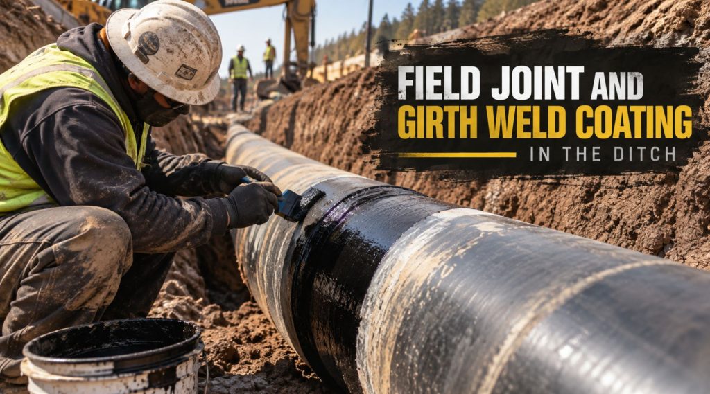
Field Joint and Girth Weld Coating in the Ditch

There’s a moment on almost every pipeline construction spread where the mainline coating stops mattering for a second, and everyone’s attention shifts to a six-inch band of bare steel sitting in a trench. That band is the girth weld, the spot where two lengths of factory-coated pipe were joined in the field, and it’s the one piece of the entire pipeline that never saw a coating plant. Everything else on the line got its protection under controlled conditions, heated, cleaned, and cured indoors. The girth weld gets coated outside, in whatever weather shows up that day, by a crew working against a schedule that doesn’t care much about humidity or wind.

That’s the whole story of pipeline girth weld coating in one sentence: it’s the best coating system in the world applied under the worst conditions the job can throw at it. Get it right and nobody ever thinks about that joint again for forty years. Get it wrong and you’ve built a corrosion initiation site into a pipeline that otherwise had every reason to perform.

This piece walks through what actually happens at the ditch when a field joint gets coated, why the process deserves more attention than it usually gets, and what separates a joint that holds up from one that becomes tomorrow’s excavation.

Why the Girth Weld Is the Weak Link in the System

Mainline pipe typically arrives at the spread with a factory-applied coating already in place, whether that’s fusion bonded epoxy, a three-layer polyethylene system, or another mill-applied product. That coating went on in a plant with consistent surface prep, controlled temperature, and quality checks built into the line. None of that exists at a field joint. The weld itself has to stay bare until it’s welded, x-rayed, and accepted, which means every girth weld arrives at coating time as an isolated patch of uncoated steel sitting between two coated sections, usually somewhere between four and twelve inches wide depending on cutback length and pipe diameter.

That gap has to be bridged with a coating applied on-site, and it has to bond not just to bare steel but to the cut edge of the existing mill coating on either side, a transition zone that’s a common origin point for disbondment if it isn’t handled correctly. Add in the fact that this work often happens in a trench, sometimes below grade, sometimes with groundwater intruding, sometimes in weather nobody would choose for a coating job if the schedule allowed for waiting, and it becomes clear why field joints show up disproportionately often in pipeline failure investigations relative to the small fraction of total pipe surface they represent.

What “In the Ditch” Actually Changes

A lot of technical literature on pipeline coating reads as if every application happens on a clean, dry, temperature-controlled surface. Field joint coating rarely gets that luxury. Working in the ditch means the crew is often coating below the surrounding grade, sometimes with limited headroom to maneuver blasting or spray equipment around the pipe, and frequently on a compressed timeline because the trench can’t stay open indefinitely once tie-in welding is complete.

Weather is the other variable that separates ditch work from shop work. Rain, wind-driven dust, and temperature swings between morning and afternoon all affect surface preparation quality and coating cure in ways a coating plant simply doesn’t have to manage. A crew that would happily wait out a dust storm on a controlled job often can’t afford to on a linear construction spread moving at a set number of joints per day. That production pressure is real, and it’s exactly why field joint coating procedures need to be specific, repeatable, and resistant to being shortcut when the day is running long.

Surface Preparation at the Joint Comes First, Every Time

Nothing about field joint coating matters if the surface prep underneath it is inadequate, and that’s true across every coating type on this site, not just field joints specifically. Our guide on properly preparing a pipeline surface before coating lays out the abrasive blast standards that apply here, and at a girth weld the requirement is usually stricter than what a lot of crews expect, because the joint is carrying the full corrosion-protection burden with no mill coating underneath to fall back on.

Near-white metal blast per NACE No. 2 / SSPC-SP 10 is the typical baseline for buried spray-applied field joint coatings, with an anchor profile in the 2.5 to 4.5 mil range depending on the specific product’s technical data sheet. The bare steel band needs full profile, but so does the transition zone where the new coating overlaps the cut edge of the factory coating, and that overlap area gets missed more often than it should. A rushed feathering or bevel on the mill coat edge leaves a step that the field joint material has to bridge, and a poor bridge there is one of the more common places disbondment actually starts. Weld spatter, arc strikes, and any residual welding slag also need to be fully removed before blasting, since coating over any of that essentially guarantees a defect at that exact spot.

Coating Options for Field Joints

Three broad categories cover most field joint work, and the right one depends on the pipe’s mainline coating, the service environment, and how much time the crew realistically has at each joint.

Heat-shrink sleeves remain common for field joints paired with FBE or three-layer mainline coatings, using a radiation-crosslinked polyethylene backing with a hot-melt adhesive that bonds to the pipe and the mill coating edges once heated. They’re relatively fast to install and don’t require spray equipment, which is part of their appeal on remote spreads, but installation quality is entirely dependent on getting the heat and pressure right, and improperly shrunk sleeves are a well-documented source of tenting and voids.

Liquid epoxy and two-part liquid coatings get applied by brush, roller, or low-pressure spray directly onto the prepared joint, curing over a period of hours rather than seconds. They’re a reasonable option for irregular joint geometry or repair situations, though cure time on a cold or wet day can stretch out in ways that hold up the whole crew behind that joint.

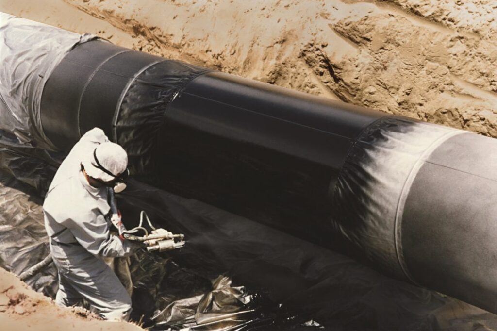
Spray-applied polyurea and polyurethane systems have become the fastest-growing choice for field joints specifically because they solve the production-rate problem. Gel times under five seconds mean a joint can be coated and ready to backfill in a fraction of the time a liquid epoxy needs to cure, without sacrificing the flexibility that a rigid coating lacks. Our guide on why polyurea has become the go-to pipeline coating covers the underlying chemistry, and the same properties that make it attractive on rehab work, fast cure, high elongation, strong adhesion to properly prepped steel, are exactly what a field joint crew needs when the ditch can’t stay open all week.

Field Joint SystemTypical Cure/Set TimeEquipment NeededBest FitWatch-Out
Heat-shrink sleeveMinutes (heat-activated)Propane torch, rollersFBE or 3LPE mainline, moderate soilsImproper heat/pressure causes tenting
Liquid epoxyHoursBrush/roller/low-pressure sprayIrregular geometry, repairsSlow cure holds up backfill schedule
Spray polyurea/polyurethaneSeconds to minutesPlural-component spray rigHigh-production spreads, HDD tie-ins, aggressive soilsRequires trained applicator and proper equipment maintenance

For a broader comparison of how these categories stack up against factory-applied mainline systems, our guide on pipeline coating systems compared, FBE, tape, and spray-applied goes into more depth on where each one fits across the full pipeline lifecycle, not just at the joint.

Thickness and Holiday Testing Don’t Get a Pass at the Joint

It’s tempting to treat the field joint as a smaller version of the mainline spec, but thickness requirements at the joint are often driven by different considerations, mechanical protection during backfill, soil stress at a point where pipe stiffness changes slightly, and the fact that the joint has no factory coating to share the load with. Our detailed breakdown of polyurea coating thickness for pipeline service explains the relationship between dry film thickness and holiday frequency, and that relationship matters even more at a field joint, where a single missed spot in a narrow coated band represents a much larger share of the total protected surface than a comparable holiday would on hundreds of feet of mainline pipe.

Holiday testing every joint before backfill isn’t optional on a well-run spread, even though it slows the crew down slightly. A high-voltage spark tester calibrated to the coating’s specified thickness catches pinholes and thin spots that visual inspection alone will miss, and catching them before the trench closes is immeasurably cheaper than catching them during an integrity dig fifteen years later.

Cathodic Protection Has to See the Joint, Too

A pipeline’s cathodic protection system is designed around the assumption that the coating is doing most of the corrosion-prevention work, with CP picking up the small percentage of area where coating defects exist. Field joints complicate that picture slightly, since they’re a known, concentrated area where coating quality varies more than it does on mill-coated pipe. Our explainer on how cathodic protection interacts with pipeline coatings covers this relationship in more general terms, but the practical takeaway for field joints specifically is that CP effectiveness at a disbonded or holidayed joint depends heavily on electrical continuity through the surrounding soil, which isn’t guaranteed at every joint location, particularly in rocky ditch conditions or where backfill material varies from the rest of the right-of-way.

Where Field Joints Actually Fail

Nearly every root cause behind a failed field joint traces back to one of a handful of repeatable issues rather than something exotic. Our root cause analysis of pipeline coating failures covers the broader failure landscape across coating types, and field joints show up disproportionately in that data for reasons that are almost always preventable at the time of installation.

Inadequate surface preparation, especially at the transition zone with the mill coating, is the single most common thread. Moisture on the steel at the time of application, whether from rain, condensation, or a joint coated too soon after a weld cooled in humid conditions, is close behind. Rushed cure time on liquid systems, where a crew backfills before the coating has actually reached handling strength, causes mechanical damage that isn’t visible until the joint is excavated years later. And mismatched coating chemistry, where a field joint product isn’t actually compatible with the mainline coating it’s supposed to bond to, creates an adhesion problem baked into the joint from day one.

Things to Consider Before Specifying a Field Joint Coating System

  1. What’s the mainline coating, and has the field joint product actually been tested and approved for adhesion compatibility with it?
  2. What production rate does the spread need per day, and does the coating’s cure time realistically support that schedule without cutting corners?
  3. What are the actual ditch conditions, moisture, temperature range, and access constraints, at the time of year construction is planned?
  4. Is holiday testing built into the daily workflow before backfill, or is it something that happens only when someone remembers?
  5. Does the transition zone at the mill coating cut edge get its own inspection step, separate from checking the bare-steel band?

Frequently Asked Questions

What is a girth weld field joint in pipeline construction?

It’s the section of bare pipe left uncoated at the factory so the joint can be welded in the field once two pipe sections are aligned. Once the weld is completed and inspected, that band of bare steel and the adjacent cut edges of the mill coating need their own coating applied on-site before backfill.

Why can’t field joints just use the same coating as the rest of the pipe?

Mainline coatings like FBE or 3LPE are applied under factory conditions that can’t be replicated in a trench. Field joint coatings are formulated and selected specifically for field application, often prioritizing fast cure and forgiving application conditions over the exact chemistry used at the mill.

How thick should a field joint coating be?

It depends on the coating system and soil conditions, but spray-applied field joint systems commonly run in a similar range to mainline polyurea specs, with aggressive soils or rocky backfill pushing toward the higher end of typical thickness ranges. The coating manufacturer’s technical data sheet should always be the final word for a specific product.

Does weather actually affect field joint coating quality?

Yes, significantly. Moisture on the steel surface, wind-blown dust re-contaminating a blasted surface, and temperature extremes affecting cure time all have a measurable effect on field joint performance, which is part of why procedures often specify minimum and maximum application temperatures and require protection from precipitation during application.

How is a field joint coating inspected before backfill?

Visual inspection, dry film thickness measurement, and holiday testing with a properly calibrated spark tester are standard steps. Adhesion testing is sometimes specified for a sample percentage of joints, particularly on larger projects or where a new applicator crew is being qualified on the job.

Conclusion

Every pipeline is only as strong as its weakest coated section, and on most projects, that weakest section is sitting in the ditch at a girth weld rather than anywhere along the factory-coated mainline. The coating going onto that joint has to do everything the mill coating does, bond to bare steel, resist soil stress, hold up cathodic protection continuity, without any of the controlled conditions that made the mill coating reliable in the first place. Treating field joint coating as a rushed afterthought behind the more visible work of welding and tie-in is one of the more common ways operators end up funding an unplanned dig years down the line. Getting surface prep right at the transition zone, matching the coating system to the mainline chemistry and the actual ditch conditions, and holiday-testing every joint before backfill are what separate a field joint that quietly does its job for decades from one that becomes the reason a crew is back out on the right-of-way sooner than anyone planned.

Read More

Artificial Intelligence (AI) is revolutionizing the way pipelines are managed

The pipeline integrity industry is crucial for ensuring the safe and efficient transportation of oil, gas, and other fluids. With thousands of miles of pipelines stretching across the globe, it’s essential to have robust systems in place to monitor and maintain their integrity. Artificial Intelligence (AI) is revolutionizing the way pipelines are managed, offering advanced solutions that enhance safety, reduce costs, and improve efficiency.

AI technology, including machine learning and data analytics, can be applied at various stages of the pipeline integrity management process. Let’s explore some of the key applications and benefits of using AI in the industry.

  1. Predictive Maintenance: AI can enable predictive maintenance by analyzing real-time data from sensors installed along the pipeline. By continuously monitoring parameters such as pressure, temperature, and flow rate, AI algorithms can identify patterns and anomalies that indicate potential issues. This proactive approach helps to prevent failures, reduce downtime, and optimize maintenance activities.
  2. Leak Detection: One of the most critical aspects of pipeline integrity is detecting leaks promptly. AI algorithms can analyze data from multiple sources, including acoustic sensors and satellite imagery, to identify leaks accurately. By comparing current data against historical patterns, AI can assess whether a leak exists, locate its precise position, and estimate its severity. Early detection of leaks improves environmental protection and minimizes the risk of accidents.
  3. Corrosion Monitoring: Corrosion is a significant threat to the integrity of pipelines, and timely detection is crucial to prevent catastrophic failures. AI systems can analyze data from corrosion sensors, cathodic protection systems, and other sources to identify areas prone to corrosion. Machine learning algorithms can predict corrosion rates based on historical data and provide recommendations for mitigating the problem. This proactive approach helps operators implement appropriate preventive measures and extend the lifespan of pipelines.
  4. Risk Assessment: AI can facilitate comprehensive risk assessments by analyzing vast amounts of data, including historical records, inspection reports, and environmental factors. Machine learning algorithms can identify potential risks, such as soil movement, natural disasters, or equipment aging, and calculate their likelihood and potential impact. This information allows operators to prioritize maintenance activities and allocate resources effectively, improving safety and cost savings.
  5. Pipeline Monitoring: AI-powered systems can continuously monitor pipelines using a combination of sensors, drones, and satellite imagery. Real-time data can be analyzed with historical information to detect anomalies, such as vibrations or temperature variations, that may indicate potential issues. Rapid identification of abnormal behavior allows for swift response, preventing accidents and minimizing the impact on operations.
  6. Decision Support: Integrating AI systems with existing pipeline integrity management software provides operator decision support capabilities. AI algorithms can analyze data, identify trends, and make predictive recommendations regarding pipeline maintenance, repairs, or replacement. This data-driven approach helps operators optimize their decision-making process, reduce costs, and improve overall pipeline integrity.
  7. Regulatory Compliance: The pipeline industry is subject to stringent regulations to ensure safety and environmental protection. AI can assist operators in complying with these regulations by providing accurate data analysis, reporting, and documentation. AI systems can automatically generate compliance reports, flag potential violations, and provide real-time information to regulatory authorities, streamlining the regulatory process and reducing administrative burden.

In conclusion, the use of AI in the pipeline integrity industry is transforming the way pipelines are monitored and managed. From predictive maintenance and leak detection to risk assessment and regulatory compliance, AI-powered systems offer significant benefits. By leveraging the power of AI, operators can enhance safety, reduce costs, optimize maintenance activities, and improve overall pipeline integrity. As technology continues to advance, the pipeline integrity industry can expect further improvements driven by AI innovations.

Read More

Enhancing Pipeline Integrity: The Advantages of Automatic Internal and External Pipeline Coatings


Pipelines play a vital role in the transportation of fluids, such as oil, gas, and water, across vast distances. To ensure their longevity and structural integrity, pipelines require protective coatings. In recent years, automatic internal and external pipeline coatings have gained prominence as versatile solutions for enhancing pipeline durability. In this blog post, we will explore the advantages of these coatings, their application processes, and how they contribute to the overall maintenance and performance of pipelines.


I. Understanding Automatic Internal Pipeline Coatings
Automatic internal pipeline coatings, also known as pipeline lining or pipe rehabilitation, involve the application of specialized coatings to the inner surface of pipelines. These coatings serve various purposes, such as corrosion prevention, reduction of frictional resistance, and enhancement of fluid flow.

1. Corrosion Prevention:
Internal pipeline coatings act as a physical barrier between corrosive fluids and the pipe’s wall, shielding it from chemical reactions. They are designed to withstand the harsh conditions inside the pipeline, thereby extending its service life.

2. Enhanced Flow Efficiency:
The smooth surface provided by internal coatings reduces frictional resistance, ensuring a more efficient flow of fluids. This not only maximizes the pipeline’s capacity but also reduces energy consumption, contributing to cost savings.

3. Reduced Maintenance Costs:
The protective barrier created by these coatings minimizes the need for regular maintenance and repair. This leads to significant cost reductions over the pipeline’s lifetime.

II. Exploring Automatic External Pipeline Coatings
Automatic external pipeline coatings involve the application of coatings on the outside surface of pipelines to protect against external factors such as corrosion, abrasion, and environmental conditions.

1. Corrosion Protection:
External pipeline coatings shield the pipeline from corrosive elements in the soil, water, or atmosphere. These coatings act as a barrier, preventing direct contact between the pipeline and the corrosive agents, thereby reducing the risk of corrosion-related damages.

2. Impact and Abrasion Resistance:
External pipeline coatings provide a protective layer that helps withstand impacts from external objects and resist abrasion caused by soil movement or contact with machinery. This aspect extends the pipeline’s durability, even in challenging terrain or harsh operating conditions.

3. Environmental Protection:
Automatic external coatings also provide insulation against temperature fluctuations, protecting the pipeline from extreme heat or cold. Additionally, they act as a barrier against UV radiation, preventing degradation caused by prolonged exposure to sunlight.

III. The Application Process of Automatic Internal and External Pipeline Coatings
1. Surface Preparation:
Before applying any coating, proper surface preparation is essential. Both internal and external pipeline surfaces must be cleaned thoroughly to remove contaminants, rust, or old coatings that could affect the adhesion of the new coatings.

2. Coating Application:
a. Internal Pipeline Coatings:
Internal coatings are typically applied using automated internal pipe coating equipment. This equipment sprays or flows the coating material uniformly along the pipeline’s inner surface, ensuring complete coverage. The coatings are then cured using heat or UV light, depending on the specific coating material.

b. External Pipeline Coatings:
External pipeline coatings are applied either by manual or automated methods. The manual application involves using brushes, rollers, or sprayers to evenly distribute the coating material. In contrast, the automated application utilizes specialized equipment, such as robotic systems, for precise and efficient coating application.

3. Quality Control and Inspection:
After the coatings are applied, thorough quality control and inspection procedures are carried out to ensure adherence to standards and specifications. This includes testing for coating thickness, adhesion, and overall quality.

IV. Conclusion
Automatic internal and external pipeline coatings offer significant benefits in terms of corrosion prevention, enhanced flow efficiency, reduced maintenance costs, and protection against environmental factors. The application process, including proper surface preparation and careful coating application, ensures optimal performance and longevity of the coatings. By incorporating these coatings into pipeline infrastructure, industries can enhance their operational reliability, reduce environmental impact, and minimize overall maintenance costs, ultimately ensuring the efficient transport of vital fluids across long distances.

Read More

Why polyurea has become the go to oil pipeline coating

THE GO TO OIL PIPELINE COATING

olyurea is quickly becoming the go-to coating for oil pipelines, as it provides superior protection against corrosion compared to traditional coatings. It’s a two-component material that is sprayed on the surface of a pipe and cures into a seamless barrier that not only prevents rust and other elements from corroding the pipeline, but also helps maintain its structural integrity.

The use of polyurea in oil pipeline coatings has been steadily increasing over the past few years due to its many advantages over other types of pipeline coatings. Its superior resistance to corrosion makes it ideal for protecting pipelines from the harsh environmental conditions they are exposed to every day. Polyurea can stand up to high temperatures, high pressure, harsh chemicals, and even ultraviolet light without breaking down or losing its effectiveness. This makes it ideal for use in offshore drilling operations where there are often nearby sources of water and other fluids that can corrode unprotected pipes.

WHAT IS POLYUREA?

Polyurea is a coating material used in various industrial applications for decades, including oil and gas pipeline coatings. It is a thermosetting resin that forms when two components are mixed and then cured. Polyurea coatings have excellent physical properties such as flexibility, high tensile strength, chemical resistance, abrasion resistance, tear resistance and low moisture absorption. These properties make polyurea well-suited for use in offshore or subsea oil and gas pipelines that must withstand extreme environmental conditions.

Polyurea has many advantages over traditional pipeline coatings such as epoxy or polyurethane. One of the most important advantages is its fast curing time; when applied to a surface, polyurea can harden within minutes rather than hours or days as with other materials. This makes it an ideal choice for quick repairs or installation in remote sites as well as emergencies. Polyurea is highly resistant to corrosion, which allows it to perform extremely well in wet environments such as water treatment plants and marine applications.

In terms of its composition, polyurea consists of two components that react with each other during the application process. The first component comprises isocyanates while the second contains active hydrogen compounds such as amines or alcohols. When these two components come into contact with each other, they form a polymer chain that binds them together and creates the resulting coating material. For this process to occur properly, the correct ratio of Isocyanate to Hydrogen Compound must be maintained during the mixing process; if this ratio is not met, then the resulting product will be weak or brittle and easily damaged by environmental factors such as heat and cold temperatures or UV radiation exposure.

When applied correctly, polyurea coatings can protect from abrasive elements such as sand particles and saltwater spray found in offshore environments while also providing insulation against thermal shock from temperature changes due to seasonal weather variations. Polyurea can also serve as a vapor barrier keeping corrosive gases out while allowing moisture trapped inside surfaces to escape without causing damage.

Due to its impressive performance characteristics and versatility across multiple industries, including oil refinery operations and water treatment systems, polyurea is becoming increasingly popular among engineers for any number of projects requiring top-quality protection from harsh environmental conditions or demanding mechanical stressors like vibration or movement caused by waves or tides at sea level installations. It’s important, however, that proper application techniques are followed strictly during installation; otherwise, premature failure may result due to improper mixing ratios or improper curing times, so experienced professionals should always be consulted prior to beginning work on any project involving this material to maximize performance and longevity results upon completion.

BENEFITS OF USING POLYUREA FOR PIPELINE COATING

A major benefit of using polyurea as an oil pipeline coating is its ability to be applied quickly and easily. Traditional coatings can take days or weeks to cure properly, whereas polyurea can be applied in just minutes with no curing time required. This allows for significantly faster completion times on projects involving large pipelines and reduces installation costs significantly compared to other types of coatings. It also helps reduce labor costs since fewer workers are needed to install it than with other coatings, which can sometimes require large teams of workers working long hours over several days or weeks.

In addition to its superior resistance to corrosion and ease of application, polyurea has excellent adhesion properties that make it capable of forming a strong bond with various surfaces, including steel and concrete. This ensures that any cracks or weak spots in the pipe wall are sealed securely, preventing any further damage from occurring inside the pipe wall over time due to leaks or corrosion. Its flexibility also allows it to expand and contract with changes in temperature without cracking or failing like some traditional coatings would do under similar conditions.

Polyurea also offers excellent insulation properties that help prevent heat loss during transport, which helps reduce energy costs associated with shipping crude oil through long distances via pipelines and reduces heat loss during refining processes at refineries located near production sites. In addition, polyurea does not contain any volatile organic compounds (VOCs) so there is no need for special permitting related VOC emissions when applying the coating onsite at production facilities – this benefits both environmental safety and cost savings associated with avoiding permit fees or additional fines imposed by regulatory bodies related VOC emissions near production sites.

Finally, one last benefit of polyurea is its low maintenance requirements throughout a pipeline’s lifespan due mostly to its durability and resistance against harsh elements such as UV rays, temperatures extremes, solvents, salt water exposure etc… All these factors combined make polyurea one of most effective yet cost-efficient solutions available today when it comes selecting an appropriate coating option for oil pipelines used in transporting crude oil around the world safely and efficiently while ensuring regulatory compliance necessary ensure safety standards followed around workplace environments near production sites where employees come into contact with hazardous materials involved in drilling operations worldwide each day without fear of health risks associated possible exposure aforementioned elements involved drilling process itself otherwise might result costly lawsuits company itself should an unfortunate incident occur premises work .    With all these advantages taken into consideration , it’s no wonder why more companies are opting use polyurea as their choice coating solution when constructing new oil pipelines looking to extend life existing ones currently service .

Read More

WHY POLYUREA IS CRUCIAL TO THE OIL AND GAS INDUSTRY

Polyurea is a remarkably strong spray coating that is utilized in a variety of applications in a variety of industries. There are many advantages of making use of polyurea in the field of oil and gas. It effectively shields storage tanks for gas and oil pipelines, containers, and tanks from abrasion, weather, and chemical corrosion, and also extends the life span of these pipelines and tanks.

While other coatings for protection such as polyurethane and epoxies are employed, polyurea is a newer and much more durable waterproofing and protection system.

Here are some ways polyurea coatings can be utilized for oil and gas production.

Protection against Harsh weather conditions

Polyurea is applied in a liquid spray and it dries in just a few minutes, forming a durable membrane. After the surface has completely dried, it can be used immediately and endure extreme weather conditions such as snow and ice, as well as rain as well as prolonged exposure to U.V. radiation from the sun. This is what makes polyurea the perfect protective coating for all surfaces that are exposed to sunlight.

Refurbish Pipeline Tanks and Rollers

With time, continual use and exposure to extreme chemicals can gradually strip away protective coatings that protect your tanks. If properly maintained, polyurea coatings can extend the life of tanks more than other coatings that have been utilized previously. Polyurea coatings are able in order to refurbish pipeline rollers as well as the interior tank linings to prolong their lifespan and avoid corrosion.

Increase the durability and Safety Standards

With strong physical as well as elastomeric properties, polyurea can be used to construct secondary and primary containment liner for storage tanks, which will stop chemicals from spilling out. The enhanced safety features shield workers working in the oil and gas industry from the risk of exposure and explosions caused by chemical interactions. They also shield the surrounding environment from pollution.

Polyurea membranes stand up against extreme temperature and are employed for both indoor and outdoor industrial applications like helicopter pads, walkways floor tiles for workshops, lining tanks and more.

Top Coat Oil and Gas Pipes

If you are working on an oil or gas pipeline Some of the most significant risk factors are corrosion as well as corrosion, chemical leaks, and abrasion. Polyurea coatings are applied as an additional layer of protection on pipelines and tank linings in order to ensure that safety standards are met and safeguard workers from injury and damage.

Tank Coating

On drilling rigs for oil or gas storage tanks are regularly exposed to potentially hazardous chemicals as well as weather conditions. Covering the inside containers with a long-lasting polyurea coating will help regulate the temperature inside, stop the buildup of pressure that can cause explosions, and also seal any holes or damages that could cause harmful chemical leaks.

ArmorThane is among the most prominent suppliers of premium polyurea products that provide excellent protection coating products for use in the gas and oil industries. Contact them today to find out how they can help you!

Read More