
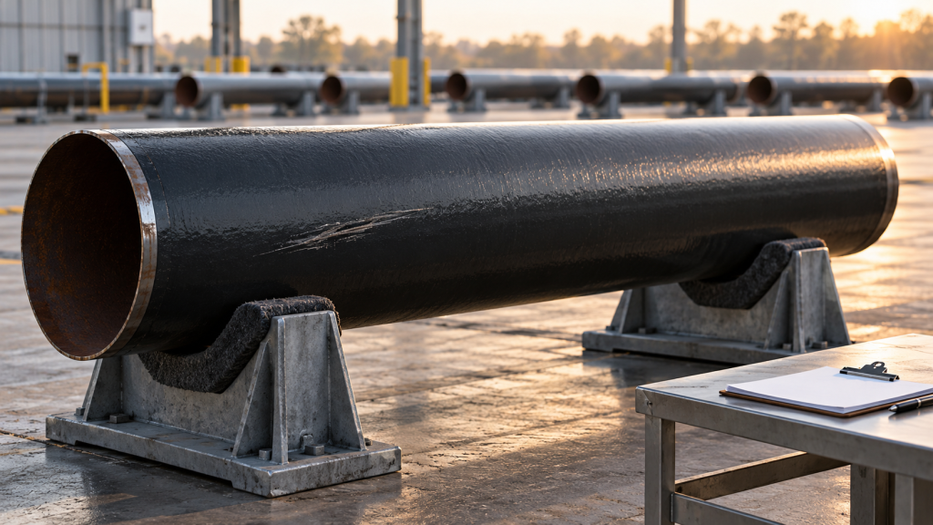
Receiving Coated Pipe: Damage Checks Before Storage and Installation
Coated pipe can pass a factory inspection and still arrive at the installation area with damage. Transport restraints, unloading, storage and later moves create additional opportunities for a coating to be marked or damaged. A receiving check is therefore useful early in the job, while the delivery and affected pipe can still be identified.
The objective is to recognize concerns, prevent questionable material from moving forward unnoticed and route decisions to qualified personnel. This is a coordination checklist, not a rigging plan, coating-repair specification or substitute for the operator’s inspection procedures.
Separate receiving from installation acceptance
For pipeline construction subject to the relevant U.S. Part 195 requirements, 49 CFR 195.206 requires visual inspection of pipe and other components at the installation site for damage that could impair strength or serviceability. Signing a delivery receipt does not complete that later responsibility.
There is also a specific coating checkpoint. Section 195.561 requires inspection of the external coating covered by section 195.557 just before the pipe is lowered into the ditch or submerged, with discovered coating damage repaired. Schedule receiving, intermediate checks required by the project, and this final checkpoint as identifiable events.
Confirm the requirements that apply to the particular pipeline. These provisions should not be presented as a universal inspection rule for every type of pipe or facility.
Prepare the receiving decision before the truck arrives
Have the purchase documents, approved coating system and supplier’s handling instructions available to the receiving team. Agree how pipe identifiers will connect the physical delivery with its paperwork. The team also needs a clear way to distinguish material awaiting evaluation from material released for the next operation.
A practical receiving record can capture:
- Delivery date, shipment reference and receiving location
- Pipe identifiers and the coating system stated in the delivery documents
- Visible concerns, with photographs tied to each affected identifier
- Any areas that could not be inspected safely at that stage
- The person notified and the current disposition of the affected material
Record missing information as missing. A delivery quantity that matches the order does not resolve an uncertain coating identity or an unreadable pipe marking.
Look for changes that need qualified assessment
Within the approved inspection arrangement, record visible cuts, scraped areas, cracking, loose coating edges, exposed metal and unusual marks at support or restraint locations. Describe what is visible without deciding from a photograph alone how deep the damage extends. A useful photograph includes enough surrounding detail to locate the mark as well as a closer view.
Damage to the steel needs its own evaluation. A suspected dent, gouge or distorted end should not be treated as a coating-only problem simply because a repair material could cover it. Refer uncertain conditions to the operator’s designated inspection or engineering personnel before the pipe proceeds.
Inspection access must be planned with the handling crew. Nobody should climb an unstable stack, reach between unsecured pipe or stand beneath a suspended load to complete a checklist. If the underside is inaccessible, record that limitation and arrange safe access through the approved handling plan.
Protect the coating during storage and subsequent moves
The receiving conversation should include how the pipe will be supported, separated, lifted and moved next. Obtain the supplier’s requirements for the actual coating system, including any storage-duration or environmental restrictions. Do not choose stack heights, support spacing or lifting methods from a general coating article.
49 CFR 195.559 includes resistance to handling damage and soil stress among the requirements for the external corrosion-control coating within its scope. That material requirement does not establish that a particular delivered pipe section has remained undamaged through every move.
Ask the project team to identify when another condition check is required, such as after a reported impact or an unplanned move. Make it easy for the handling crew to report an event without having to decide whether the damage will eventually be acceptable. Keep the affected pipe’s status visible until that question is resolved.
Agree who can inspect, repair and release
Section 195.204 requires operator personnel performing construction inspection to be trained and qualified for the phase inspected. It also prevents an operator employee from performing the required inspection of a construction task that employee carried out. Assign responsibilities accordingly where the provision applies.
For a coating concern, obtain the approved disposition and repair procedure for the identified system. The project should establish the materials, preparation, application conditions, cure and reinspection requirements. Avoid accepting an improvised touch-up because its color resembles the surrounding coating.
Keep original findings connected to the repair and subsequent acceptance record. If work remains open, identify the next required action and the person responsible. The site’s pipeline coating handover guide explains how those records can remain usable after construction.
Carry the condition history to the final checkpoint
Before installation, reconcile the actual pipe identifiers with open receiving concerns, handling-event reports and completed repairs. Confirm that the required final inspection can occur at the correct time with safe access. Earlier photographs help explain the history, but they cannot show damage that happened after they were taken.
A useful receiving process gives the next crew a clear starting point: what arrived, what needs attention and what has been released. Preserving that information through storage and handling helps the final inspection address the pipe in front of the inspector.
Refinery Floor Coating Chemical Resistance: Process Area Floors and Thermal Shock
Walk a refinery process unit after a rough week and the floors tell the story. Dark staining under a pump seal. A pale bloom where something acidic dripped. A hairline crack along a joint that wasn’t there at the last turnaround. Refinery floor coating chemical resistance is usually the first question anyone asks when a pad needs protection, and it’s a fair one. But the floors that fail early tend to fail for a second reason too: heat. A hot fluid landing on cold concrete, or a steam hose passing over a coated pad, does damage that no chemical resistance chart ever mentions. This guide covers both problems, how they interact, and how to match a floor system to what your process area actually sees.
What a Refinery Process Floor Actually Goes Through
Most industrial floors deal with one or two kinds of abuse. A refinery process floor gets nearly all of them. Hydrocarbons of every weight drip from pump seals, sample points, and flanges. Solvents, caustic from treating operations, and acids in certain units all find their way onto concrete sooner or later, along with amines, process water carrying chlorides, and whatever cleaning chemicals the crews use afterward. On top of the chemistry, there’s heat from hot oil leaks and steam cleaning, daily temperature swings, vacuum trucks, maintenance vehicles, dropped tools, and scaffolding dragged across the surface.
Bare concrete handles almost none of this well. It’s porous, so hydrocarbons wick deep into the slab. Acids attack the cement paste and leave a dusty, weakened surface. Once concrete is saturated with oil, it’s slippery, hard to clean, and a housekeeping headache that never really goes away. A good floor system gives you a dense, cleanable barrier that keeps spills on the surface where they can be removed instead of soaking in where they can’t.
Refinery Floor Coating Chemical Resistance: What the Ratings Actually Tell You
Here’s where a lot of specifications go wrong. A chemical resistance chart lists chemicals, but the rating attached to each one depends on conditions that are easy to overlook: concentration, temperature, and how long the coating stays in contact.
Most ratings describe splash and spill exposure with reasonably prompt cleanup, which is a very different situation from continuous immersion. A pump pad that sees occasional drips is a completely different problem from a sump or trench holding process liquid for days. A coating that handles one comfortably can fail quickly in the other, even though the chemical on the chart is identical.
Concentration matters just as much. A dilute acid and a concentrated one can behave nothing alike against the same coating, and higher temperatures speed up chemical attack, sometimes dramatically. Mixtures complicate things further. A blend of solvents can be harder on a coating than any one component alone.
So the practical advice is simple. Don’t accept “chemical resistant” as an answer. Ask the manufacturer for documented resistance data covering the exact chemicals, concentrations, and temperatures your area sees, and be clear about whether the exposure is occasional splash or sustained contact. For critical areas, a test patch or immersion testing on the actual system is cheap compared with relining a unit.
Thermal Shock: The Failure Nobody Sees Coming
A coating and the concrete underneath it expand and contract at different rates. When temperatures change slowly, that mismatch is manageable. When they change fast, it isn’t. A steam hose passing over a pad, a hot process fluid spilling onto cold concrete, or a hard rain hitting a sun-baked slab can all create sudden temperature swings, and the stress concentrates right at the bond line between coating and substrate.
That stress shows up in a few ways. Thin, rigid films can crack. Coatings with a thermal expansion rate far from concrete’s can debond in sheets. And heating a slab from above can drive moisture vapor toward the bond line, producing blisters even when the coating itself is chemically fine.
Different systems handle this differently. Thicker cementitious urethane systems are generally chosen for areas with hot washdown or hot spills, in part because their thermal behavior sits closer to concrete’s. Flexible systems with high elongation tolerate movement by stretching rather than cracking. Rigid epoxies perform well chemically but can be the most vulnerable when temperature swings are severe. There are standard tests that probe this, such as ASTM C884, which evaluates thermal compatibility between concrete and an epoxy resin overlay, but a test number is only a starting point. Ask for thermal cycling or thermal shock data on the specific system, at the temperatures your area really experiences, and check the maximum service temperature on the data sheet rather than assuming.
Comparing Common Floor System Options
| System | Chemical Resistance Profile | Thermal Shock Tolerance | Cure and Downtime | Typical Role |
|---|---|---|---|---|
| Epoxy novolac | Broad, generally stronger than standard epoxy | Limited in thin rigid films | Moderate, hours to days depending on system | General chemical process areas |
| Vinyl ester | Very strong against many acids and solvents | Varies, depends on build and formulation | Moderate, more demanding application | Severe chemical exposure |
| Urethane cement | Good, formulation dependent | Generally strong, designed for hot washdown | Moderate, thicker build | Areas with heat and washdown |
| Polyurea or hybrid polyurea | Varies, can be limited against some strong acids and solvents | Flexible, tolerates movement well | Fast, short return to service | Containment, crack bridging, tight schedules |
| Polyaspartic | Varies by formulation | Varies | Fast | Topcoat or thin-build systems |
Read that table as a starting point, not a verdict. Every row says “varies” somewhere for a reason. Two products in the same category can perform very differently, and the data sheet and resistance data for the actual product should always outrank a general comparison like this one.
It’s also worth being honest about one thing: no system wins everywhere. Fast-cure polyurea systems are attractive when downtime is the main constraint, but they aren’t automatically the right answer for a trench holding strong chemicals. Epoxy novolac and vinyl ester earn their place in severe chemical service, but they’re less forgiving of movement and heat. Matching the system to the dominant threat, rather than defaulting to whatever is most familiar, is most of the job.
Surface Preparation in Oil-Soaked Concrete
Preparation is where refinery floors get tricky. Concrete that has absorbed hydrocarbons for years holds that contamination well below the surface, and coatings don’t bond reliably to oil-saturated substrate no matter how good the product is. Depending on how deep contamination runs, preparation can mean aggressive mechanical removal of the contaminated layer, followed by profiling and repair, rather than a routine blast and coat.
Moisture testing matters here too, especially on slab-on-grade pads where vapor can push up from below, and so does adhesion testing on a trial area before committing to a full pad. The principles are the same ones covered in our guide to preparing a surface before coating application, which is written around pipelines but applies directly: remove contamination, achieve the profile the manufacturer requires, and verify instead of assuming. When floor coatings fail early, the post-mortem almost always points back to preparation, a pattern our root cause analysis of coating failures explores in more detail.
Planning Around Turnarounds and Operating Units
Most refinery floor work happens in tight windows. Planned turnarounds compress everything into a fixed schedule, and in operating units, work often has to proceed in sections around live equipment, under permits and facility safety procedures. Those procedures, along with the product’s safety data sheet, govern how and when coating work can proceed. They aren’t something to improvise around.
Cure speed becomes a real selection factor in that environment. A system that returns to service in hours instead of days can mean the difference between finishing inside the window and carrying work into the next one. Fast-cure chemistries, like the polyaspartic systems discussed in our look at rehabilitation coatings where speed and durability both matter, show how much schedule flexibility that can buy. Speed has trade-offs, though. A faster cure leaves less working time, and a system that cures quickly but doesn’t match the chemical exposure is a bad trade no matter how good the schedule looks.
Details That Decide Whether a Floor Lasts
Coatings rarely fail in the middle of a field of flat floor. They fail at details: curb bases, trench edges, drain rims, expansion joints, and transitions between different surfaces. These are the places where movement concentrates and where a thin or poorly terminated coating gives out first. Good specifications spell out how the coating terminates at curbs and drains, how joints are treated, and what sealant goes into moving joints. That sealant needs to be compatible with the same chemicals as the coating itself, or the joint becomes the weak link.
Slip resistance deserves equal attention. A smooth coating is easy to clean but treacherous when wet or oily, while a heavily textured one grips well but traps contamination. Most process areas land somewhere in between, using aggregate broadcast sized for the exposure. General workplace rules, including OSHA’s walking-working surface requirements, expect floors to be kept free of slipping hazards, so this isn’t just a comfort issue.
Process areas are often also subject to secondary containment requirements, which vary by facility, product handled, and jurisdiction. Which rules apply, and what they require of the floor and its curbing, should be confirmed for the specific site rather than assumed.
Coverage and Specification Notes
For sprayed or rolled coatings, coverage follows the standard math: one gallon at one mil covers 1,604 square feet. Thicker troweled or broadcast systems are specified by thickness and mix design instead, so quantities should always come from the manufacturer’s technical data sheet for the exact system and thickness specified, not from a general rule applied across product types.
Inspection and Maintenance
A refinery floor coating isn’t something you install and forget. Regular walkdowns catch the early signs: discoloration near spill points, softening or blistering, cracking along joints, and damage at curb bases and drain edges. Small damage deserves fast repair, because chemicals migrate under a compromised coating and spread the problem well beyond the visible spot.
Cleaning practices matter too. Aggressive solvents or the wrong detergent can slowly damage a coating that was perfectly capable of handling the process chemicals it was specified for. Keeping a simple inspection record, with dates, locations, and repair notes, makes it far easier to see whether a recurring problem is tied to a specific exposure and to plan recoats before a failure forces one.
Frequently Asked Questions
What coating is best for refinery process area floors?
There isn’t a single best choice. The right system depends on the chemicals involved, the temperatures and thermal shock the area sees, and how much downtime is available. Epoxy novolac, vinyl ester, urethane cement, and polyurea systems each have areas where they make the most sense.
How can I tell if a floor coating will resist a specific chemical?
Ask for documented resistance data at the exact chemical, concentration, temperature, and exposure type involved. For critical areas, test patches or immersion testing on the actual system give much more confidence than a general rating.
What is thermal shock, and why does it crack floor coatings?
Thermal shock is a rapid temperature change, such as a hot spill or steam cleaning on a cold slab. Because the coating and concrete expand at different rates, sudden changes create stress at the bond line that can crack or debond the coating.
Can a refinery floor be coated while a unit is operating?
Sometimes, in sections and under the facility’s permits and safety procedures. Whether it’s feasible depends entirely on the site’s rules and the specific area, and the product’s safety data sheet and site procedures should govern the work.
Does oil-soaked concrete need to be removed before coating?
Often, at least the heavily contaminated layer. Coatings don’t bond reliably to oil-saturated concrete, so contamination depth needs to be assessed and the surface prepared accordingly, with adhesion testing before the full application.
How often should refinery floor coatings be inspected?
Routine visual walkdowns should be frequent, with more formal periodic inspections scheduled according to exposure severity and the facility’s own program. High-exposure areas like trenches, sumps, and curb bases deserve more attention than open, lightly used floor.
Conclusion
Refinery floor coating chemical resistance is only half of the picture. A system can handle every chemical on the list and still fail because of thermal shock, poor preparation, or a detail at a curb or joint nobody thought about. The floors that last are the ones where the system was matched to the dominant exposure, the data behind that match was documented rather than assumed, the surface was prepared for the contamination actually present, and the details were treated as seriously as the field. Get those four things right and the floor does its job quietly. Get one wrong and the process area will let you know.

Pipeline Coating Handover: Records That Make Inspection Results Usable
A pipeline coating inspection is only useful later if someone can connect the result to the right piece of pipe, the coating system and the conditions under which it was applied. A folder of unsigned reports or photographs named by date can leave an operator with plenty of information and very little usable evidence.
A good coating handover package makes that connection clear. It should let the receiving team find a location, understand the acceptance requirements, review what was measured and see how defects were resolved. Agree on the package before coating starts, while the contractor can still capture the information efficiently.
Define the scope and the acceptance basis
Start with the work covered: factory coating, field joints, rehabilitation or individual repairs. Identify the approved coating system, project specification, inspection and test plan, application procedure and document revisions. List the responsible contractor, inspector and person authorized to release the work.
Standards have specific scopes. For example, ISO 21809-3:2016 addresses qualification, application and testing of field-joint corrosion coatings. Its published scope excludes additional mechanical protection, thermal insulation and concrete weight-coating joint infill. If those layers are included in the project, make their acceptance evidence identifiable too. Avoid treating one coating certificate as approval of the complete joint assembly.
Use the contractually applicable editions and approved procedures. A public summary of a standard cannot supply every acceptance limit or replace the controlled documents used on the job.
Give each coated location a traceable identity
Choose identifiers that remain meaningful after installation. Depending on the project, these could include pipe numbers, weld numbers, stationing, an agreed coordinate reference and repair numbers. Connect them to the as-built register rather than creating an unrelated numbering system for coating inspection.
For each location, link the coating product and relevant component batch numbers to the application date and crew record. Where the approved procedure requires evidence of storage conditions, shelf life or mixing, retain it with the same reference. Photographs help when their captions identify the location, orientation, date and feature being shown.
As a practical check, ask someone unfamiliar with the work to locate one photographed repair using the register. If they need the original inspector to explain it, improve the identification before handover.
Preserve the preparation and application evidence
The finished surface cannot tell the receiving team everything about the steel underneath. Keep the preparation inspection and application records required by the project, including the specified cleanliness assessments, surface-profile measurements and contamination checks where applicable.
Environmental readings should be associated with a time and work area. A temperature or humidity entry from the start of a shift may not explain conditions when another joint was coated hours later. Record application and curing information at the intervals required by the approved procedure, with any interruptions or departures documented.
This is a records checklist, not a universal preparation specification. The product, substrate, exposure and approved procedure determine which measurements and limits apply.
Make test results interpretable
A report that says “passed” should also show what was tested, how it was tested and which acceptance criteria were used. Preserve the measured results and their locations, including units. Keep instrument identification and the calibration or verification evidence required by the applicable method.
For holiday detection, DeFelsko’s ASTM G62 guidance describes reporting the specimen identity, instrument, verification method and test method. It also identifies voltage information for high-voltage testing. These details let a reviewer understand a result instead of relying on an unexplained check mark.
Record the voltage actually used and its approved basis. DeFelsko explains that insufficient voltage can miss defects, while excessive voltage can damage the coating. Selection belongs with the applicable standard, coating requirements and qualified inspection procedure. Do not insert a generic volts-per-thickness rule into the handover form.
Connect each defect to its repair and reinspection
Give every reported defect a reference that follows it through disposition, repair and acceptance. Record its location, the approved repair method, material used, repair date and subsequent inspection results. Retain the original finding alongside the closeout so the repair history remains understandable.
For U.S. pipelines subject to the relevant Part 195 requirements, 49 CFR 195.561 requires inspection of the specified external coating immediately before lowering into the ditch or submerging, and repair of discovered damage. Build the project workflow around that timing. An earlier inspection does not document damage that might occur during later handling.
Finish with an index and a clear release status
Organize the final package so a reviewer can move from the asset register to the applicable reports without guessing. A useful index groups:
- Approved specifications, procedures and revisions
- Location and material traceability records
- Preparation, application and inspection reports
- Defect, repair and reinspection records
- Approved deviations, outstanding items and release signatures
Keep unresolved items visible and distinguish a conditional release from final acceptance. Agree on the archive owner and retention schedule. 49 CFR 195.589 includes corrosion-control record requirements with different retention periods, so one blanket deletion date may be inappropriate.
The final test is simple: can the next person explain what was installed, where it was inspected and why it was accepted? A handover package that answers those questions is useful both at construction closeout and when the pipeline needs attention later.
Produced Water Tank Lining: Protection for Chloride and H2S Service
Produced water is some of the most aggressive liquid a storage tank ever has to hold, and it rarely shows mercy to whatever lining is protecting the steel underneath. It comes up alongside oil and gas carrying high chloride concentrations, often dissolved CO2, and frequently hydrogen sulfide, and that combination doesn’t just add up to ordinary corrosion risk. It compounds into something meaningfully worse than any single factor on its own. Produced water tank lining has to be chosen with that compounding effect in mind, not just rated against chloride or H2S in isolation, because a lining that handles one reasonably well can still fail fast when both show up in the same tank at the same time.
Why Produced Water Tank Lining Needs to Handle Chloride and H2S Together
Chloride-rich brine attacks carbon steel through pitting and crevice corrosion, concentrating damage at specific weak points, particularly welds, rather than spreading evenly across a surface. That localized attack is part of what makes chloride corrosion so dangerous: a tank can look structurally sound on a visual inspection while a pit is quietly working its way through the wall thickness at one specific spot.
Hydrogen sulfide brings an entirely different failure mode into the picture. In susceptible steels, H2S drives sulfide stress cracking, a brittle fracture mechanism that can develop and propagate far faster than general corrosion, particularly in high-strength steel or in areas with residual stress from welding or fabrication. H2S service also means gas permeation is a real concern for any polymer lining, since dissolved H2S can work its way into a lining’s molecular structure over time, and a sudden pressure drop, during a tank blowdown or rapid depressurization event, can cause that absorbed gas to expand explosively within the lining itself, a failure mode known as rapid gas decompression, or RGD.
Put chloride and H2S together, and add the microbial activity that’s common in produced water tanks, sulfate-reducing bacteria that both generate additional H2S and contribute to localized under-deposit corrosion, and you get an environment that demands a lining genuinely engineered for sour, saline service, not a general-purpose corrosion coating pressed into a job it wasn’t built for.
What This Means for Lining Selection
A lining suited for produced water service needs to do several things simultaneously: resist chloride-driven pitting and crevice attack at the steel interface, maintain chemical stability under sustained H2S exposure without degrading or losing adhesion, and resist gas permeation well enough to avoid blistering under the pressure cycling a produced water tank commonly experiences during normal operation.
Material qualification for sour service isn’t just a performance preference, it’s governed by industry standards, most notably NACE MR0175 and its international counterpart ISO 15156, which set requirements for materials used in H2S-containing environments in oil and gas production. Any lining specified for a produced water tank in sour service should have documented compliance with the relevant sections of that standard for the specific service conditions involved, confirmed against the manufacturer’s technical documentation rather than assumed from general marketing claims about chemical resistance.
Comparing Lining and Tank Options
| Factor | Bare Carbon Steel | Fiberglass Reinforced Plastic (FRP) | Epoxy Phenolic Lining | Spray-Applied Polyurea/Polyurethane Lining |
|---|---|---|---|---|
| Chloride pitting resistance | Poor | Good | Good when properly applied | Good when formulated for the service |
| H2S/sour service suitability | Poor, susceptible to SSC | Generally good | Varies by formulation | Varies, must be confirmed against NACE MR0175/ISO 15156 |
| Gas permeation / RGD resistance | Not applicable | Moderate to good | Moderate | Depends heavily on specific formulation |
| Application speed | Not applicable | Slower, often shop-fabricated | Moderate, multiple coats and cure time | Fast, seconds to a few hours cure |
| Repairability | Not applicable | More difficult, specialized repair | Moderate | Generally easier, can often be patched in place |
| Typical cost | Low material cost, high corrosion risk | Higher, especially for new tank construction | Moderate | Moderate, varies by formulation and film thickness |
None of these options is automatically correct for every produced water application. FRP tanks offer strong inherent chemical resistance but represent a bigger commitment, usually chosen at the point of new tank construction rather than as a retrofit lining for an existing steel tank. Epoxy phenolic systems have a long track record in oil and gas service and handle a wide range of chemical exposure well, though application and cure time are longer than a spray-applied system. Polyurea and polyurethane linings offer fast application and strong mechanical properties, but sour service suitability varies significantly by specific formulation, making that NACE MR0175/ISO 15156 qualification check a non-negotiable step rather than an assumption.
Where Tank Lining Fits Into the Broader Facility Picture
A produced water tank doesn’t operate in isolation. It’s typically part of a larger tank battery or facility that includes other storage and containment systems facing related, though not identical, exposure challenges. Our guide on tank farm coating maintenance covers the inspection cycle and recoat planning discipline that applies to produced water tanks just as much as it does to crude storage, since both need a program built around actual condition and corrosion rate data rather than a fixed calendar interval. And since produced water tanks sit within facilities that also have to meet secondary containment requirements, our piece on well pad containment systems covers the containment side of that same facility picture, spray-applied, panel, and liner approaches that protect the ground around the tank even as the tank lining itself protects what’s inside it.
Broader corrosion management also matters here. Our pipeline corrosion prevention guide covers corrosion control principles that extend well beyond pipelines into tank and vessel protection generally, and a lot of the same root-cause thinking, surface prep quality, coating selection matched to actual exposure, and ongoing inspection discipline, applies directly to getting produced water tank lining right.
Things to Consider
Confirm sour service qualification before anything else.
A lining’s general chemical resistance claims don’t substitute for documented NACE MR0175 or ISO 15156 compliance for the specific H2S concentration and partial pressure the tank will actually see. This is the detail most likely to get glossed over in a general product pitch and most important to verify directly.
Pay special attention to welds and seams during surface preparation.
Chloride pitting and crevice corrosion concentrate at these points more than anywhere else on a tank, which means lining coverage and film thickness at welds deserves extra scrutiny, not just the flat plate sections that are easier to inspect visually.
Ask about the lining’s RGD resistance if the tank sees pressure cycling.
A tank that undergoes regular pressure changes, during blowdown events or routine operational cycling, puts real stress on a lining’s resistance to gas permeation and rapid decompression. This isn’t a universal property of every polymer lining and needs to be confirmed for the specific product and service conditions.
Factor in the role of microbial activity, not just chemistry.
Sulfate-reducing bacteria are common in produced water systems and contribute both additional H2S generation and localized under-deposit corrosion. A biocide treatment program alongside the lining itself is often part of a complete corrosion management strategy, not a substitute for proper lining selection.
Plan inspection around the tank’s actual service history, not a generic schedule.
A produced water tank with documented high chloride concentration or confirmed H2S presence warrants more frequent inspection than a generic calendar-based approach would suggest, following the same risk-based logic that applies to tank inspection programs generally.
Repair Strategy When a Lining Starts to Fail
Even a properly specified lining eventually needs attention, and how that repair gets handled matters almost as much as the original specification did. A localized lining failure, whether from a weld-area chloride attack or early-stage blistering from gas permeation, doesn’t necessarily mean the whole tank needs to be stripped and relined immediately. Isolated defects identified early, before the underlying steel has taken on significant pitting or wall loss, can often be addressed with a targeted repair that matches the original lining system, provided that repair is done with proper surface preparation and genuine compatibility with the existing coating rather than a mismatched patch material applied for convenience.
The harder call comes when defects are widespread or when inspection reveals that the chloride and H2S exposure has been more aggressive than the original lining specification anticipated. In that situation, a full reline, ideally with a lining upgraded to better match the actual service conditions rather than simply replacing like for like, is usually the more defensible long-term decision, even though it costs more upfront than another round of spot repairs. Tracking the pattern of repairs over a tank’s service life, rather than treating each one as an isolated event, tends to make that full-reline decision clearer when the time actually comes, since a tank needing repeat repairs in the same areas is telling you something about whether the original lining choice actually fit the service.
Maintenance and Inspection
Holiday testing after installation or any repair work is standard practice for produced water tank linings, checking for pinholes or thin spots using methods appropriate to the lining thickness involved. Beyond initial installation, ongoing inspection should watch specifically for early signs of blistering, which can indicate gas permeation building toward an eventual RGD failure, and for any localized lining breakdown at welds or seams where chloride attack concentrates. Internal inspection intervals should follow the same risk-based framework used for tank inspection generally, adjusted for the genuinely more aggressive service conditions a produced water tank represents compared to a tank holding a less corrosive product.
Frequently Asked Questions
What makes produced water more corrosive than other stored fluids? The combination of high chloride concentration, which drives pitting and crevice corrosion, and frequent hydrogen sulfide content, which causes sulfide stress cracking and lining permeation concerns, creates a compounding corrosion risk that’s genuinely more aggressive than either factor alone.
What is NACE MR0175 and why does it matter for tank lining? It’s an industry standard, along with its international counterpart ISO 15156, governing material qualification for use in H2S-containing oil and gas environments. A lining specified for sour service produced water should have documented compliance with the relevant portions of that standard for the specific service conditions.
What is rapid gas decompression, and why does it matter for tank linings? It’s a failure mode where dissolved gas that has permeated into a polymer lining expands explosively when pressure drops quickly, causing blistering or delamination. Linings used in produced water service with H2S and pressure cycling need documented resistance to this specific failure mechanism.
Can an existing carbon steel tank be relined for produced water service, or does it need to be replaced? In many cases, an existing tank can be relined if the steel structure itself is still sound, though this requires proper inspection to confirm there’s no significant existing pitting or wall loss before applying a new lining system.
How does microbial activity affect produced water tank corrosion? Sulfate-reducing bacteria common in produced water systems generate additional hydrogen sulfide and contribute to localized under-deposit corrosion, which is why a complete corrosion management approach for these tanks often includes biocide treatment alongside proper lining selection.
Conclusion
Produced water tank lining has to be chosen for the specific, compounding reality of chloride and H2S exposure happening together, not evaluated against either threat in isolation. That means confirming documented sour service qualification against NACE MR0175 or ISO 15156, paying close attention to weld and seam coverage where chloride attack concentrates, and understanding a specific lining’s resistance to gas permeation and rapid decompression if the tank sees pressure cycling. Getting that selection right from the start, backed by proper surface preparation and a realistic inspection program afterward, is what separates a produced water tank that reaches its full service life from one that fails years ahead of schedule.
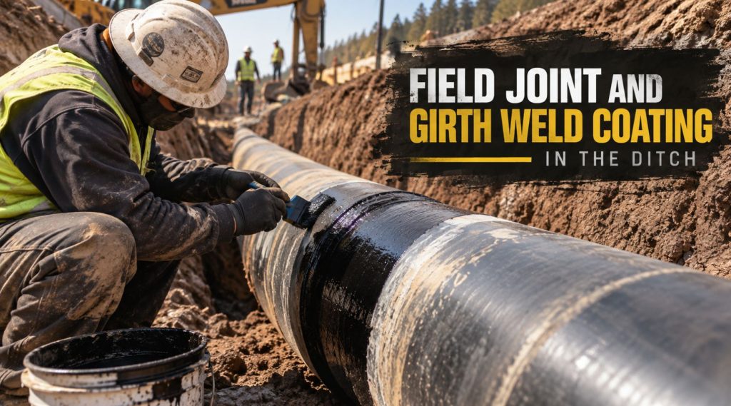
Field Joint and Girth Weld Coating in the Ditch
There’s a moment on almost every pipeline construction spread where the mainline coating stops mattering for a second, and everyone’s attention shifts to a six-inch band of bare steel sitting in a trench. That band is the girth weld, the spot where two lengths of factory-coated pipe were joined in the field, and it’s the one piece of the entire pipeline that never saw a coating plant. Everything else on the line got its protection under controlled conditions, heated, cleaned, and cured indoors. The girth weld gets coated outside, in whatever weather shows up that day, by a crew working against a schedule that doesn’t care much about humidity or wind.
That’s the whole story of pipeline girth weld coating in one sentence: it’s the best coating system in the world applied under the worst conditions the job can throw at it. Get it right and nobody ever thinks about that joint again for forty years. Get it wrong and you’ve built a corrosion initiation site into a pipeline that otherwise had every reason to perform.
This piece walks through what actually happens at the ditch when a field joint gets coated, why the process deserves more attention than it usually gets, and what separates a joint that holds up from one that becomes tomorrow’s excavation.
Why the Girth Weld Is the Weak Link in the System
Mainline pipe typically arrives at the spread with a factory-applied coating already in place, whether that’s fusion bonded epoxy, a three-layer polyethylene system, or another mill-applied product. That coating went on in a plant with consistent surface prep, controlled temperature, and quality checks built into the line. None of that exists at a field joint. The weld itself has to stay bare until it’s welded, x-rayed, and accepted, which means every girth weld arrives at coating time as an isolated patch of uncoated steel sitting between two coated sections, usually somewhere between four and twelve inches wide depending on cutback length and pipe diameter.
That gap has to be bridged with a coating applied on-site, and it has to bond not just to bare steel but to the cut edge of the existing mill coating on either side, a transition zone that’s a common origin point for disbondment if it isn’t handled correctly. Add in the fact that this work often happens in a trench, sometimes below grade, sometimes with groundwater intruding, sometimes in weather nobody would choose for a coating job if the schedule allowed for waiting, and it becomes clear why field joints show up disproportionately often in pipeline failure investigations relative to the small fraction of total pipe surface they represent.
What “In the Ditch” Actually Changes
A lot of technical literature on pipeline coating reads as if every application happens on a clean, dry, temperature-controlled surface. Field joint coating rarely gets that luxury. Working in the ditch means the crew is often coating below the surrounding grade, sometimes with limited headroom to maneuver blasting or spray equipment around the pipe, and frequently on a compressed timeline because the trench can’t stay open indefinitely once tie-in welding is complete.
Weather is the other variable that separates ditch work from shop work. Rain, wind-driven dust, and temperature swings between morning and afternoon all affect surface preparation quality and coating cure in ways a coating plant simply doesn’t have to manage. A crew that would happily wait out a dust storm on a controlled job often can’t afford to on a linear construction spread moving at a set number of joints per day. That production pressure is real, and it’s exactly why field joint coating procedures need to be specific, repeatable, and resistant to being shortcut when the day is running long.
Surface Preparation at the Joint Comes First, Every Time
Nothing about field joint coating matters if the surface prep underneath it is inadequate, and that’s true across every coating type on this site, not just field joints specifically. Our guide on properly preparing a pipeline surface before coating lays out the abrasive blast standards that apply here, and at a girth weld the requirement is usually stricter than what a lot of crews expect, because the joint is carrying the full corrosion-protection burden with no mill coating underneath to fall back on.
Near-white metal blast per NACE No. 2 / SSPC-SP 10 is the typical baseline for buried spray-applied field joint coatings, with an anchor profile in the 2.5 to 4.5 mil range depending on the specific product’s technical data sheet. The bare steel band needs full profile, but so does the transition zone where the new coating overlaps the cut edge of the factory coating, and that overlap area gets missed more often than it should. A rushed feathering or bevel on the mill coat edge leaves a step that the field joint material has to bridge, and a poor bridge there is one of the more common places disbondment actually starts. Weld spatter, arc strikes, and any residual welding slag also need to be fully removed before blasting, since coating over any of that essentially guarantees a defect at that exact spot.
Coating Options for Field Joints
Three broad categories cover most field joint work, and the right one depends on the pipe’s mainline coating, the service environment, and how much time the crew realistically has at each joint.
Heat-shrink sleeves remain common for field joints paired with FBE or three-layer mainline coatings, using a radiation-crosslinked polyethylene backing with a hot-melt adhesive that bonds to the pipe and the mill coating edges once heated. They’re relatively fast to install and don’t require spray equipment, which is part of their appeal on remote spreads, but installation quality is entirely dependent on getting the heat and pressure right, and improperly shrunk sleeves are a well-documented source of tenting and voids.
Liquid epoxy and two-part liquid coatings get applied by brush, roller, or low-pressure spray directly onto the prepared joint, curing over a period of hours rather than seconds. They’re a reasonable option for irregular joint geometry or repair situations, though cure time on a cold or wet day can stretch out in ways that hold up the whole crew behind that joint.
Spray-applied polyurea and polyurethane systems have become the fastest-growing choice for field joints specifically because they solve the production-rate problem. Gel times under five seconds mean a joint can be coated and ready to backfill in a fraction of the time a liquid epoxy needs to cure, without sacrificing the flexibility that a rigid coating lacks. Our guide on why polyurea has become the go-to pipeline coating covers the underlying chemistry, and the same properties that make it attractive on rehab work, fast cure, high elongation, strong adhesion to properly prepped steel, are exactly what a field joint crew needs when the ditch can’t stay open all week.
| Field Joint System | Typical Cure/Set Time | Equipment Needed | Best Fit | Watch-Out |
|---|---|---|---|---|
| Heat-shrink sleeve | Minutes (heat-activated) | Propane torch, rollers | FBE or 3LPE mainline, moderate soils | Improper heat/pressure causes tenting |
| Liquid epoxy | Hours | Brush/roller/low-pressure spray | Irregular geometry, repairs | Slow cure holds up backfill schedule |
| Spray polyurea/polyurethane | Seconds to minutes | Plural-component spray rig | High-production spreads, HDD tie-ins, aggressive soils | Requires trained applicator and proper equipment maintenance |
For a broader comparison of how these categories stack up against factory-applied mainline systems, our guide on pipeline coating systems compared, FBE, tape, and spray-applied goes into more depth on where each one fits across the full pipeline lifecycle, not just at the joint.
Thickness and Holiday Testing Don’t Get a Pass at the Joint
It’s tempting to treat the field joint as a smaller version of the mainline spec, but thickness requirements at the joint are often driven by different considerations, mechanical protection during backfill, soil stress at a point where pipe stiffness changes slightly, and the fact that the joint has no factory coating to share the load with. Our detailed breakdown of polyurea coating thickness for pipeline service explains the relationship between dry film thickness and holiday frequency, and that relationship matters even more at a field joint, where a single missed spot in a narrow coated band represents a much larger share of the total protected surface than a comparable holiday would on hundreds of feet of mainline pipe.
Holiday testing every joint before backfill isn’t optional on a well-run spread, even though it slows the crew down slightly. A high-voltage spark tester calibrated to the coating’s specified thickness catches pinholes and thin spots that visual inspection alone will miss, and catching them before the trench closes is immeasurably cheaper than catching them during an integrity dig fifteen years later.
Cathodic Protection Has to See the Joint, Too
A pipeline’s cathodic protection system is designed around the assumption that the coating is doing most of the corrosion-prevention work, with CP picking up the small percentage of area where coating defects exist. Field joints complicate that picture slightly, since they’re a known, concentrated area where coating quality varies more than it does on mill-coated pipe. Our explainer on how cathodic protection interacts with pipeline coatings covers this relationship in more general terms, but the practical takeaway for field joints specifically is that CP effectiveness at a disbonded or holidayed joint depends heavily on electrical continuity through the surrounding soil, which isn’t guaranteed at every joint location, particularly in rocky ditch conditions or where backfill material varies from the rest of the right-of-way.
Where Field Joints Actually Fail
Nearly every root cause behind a failed field joint traces back to one of a handful of repeatable issues rather than something exotic. Our root cause analysis of pipeline coating failures covers the broader failure landscape across coating types, and field joints show up disproportionately in that data for reasons that are almost always preventable at the time of installation.
Inadequate surface preparation, especially at the transition zone with the mill coating, is the single most common thread. Moisture on the steel at the time of application, whether from rain, condensation, or a joint coated too soon after a weld cooled in humid conditions, is close behind. Rushed cure time on liquid systems, where a crew backfills before the coating has actually reached handling strength, causes mechanical damage that isn’t visible until the joint is excavated years later. And mismatched coating chemistry, where a field joint product isn’t actually compatible with the mainline coating it’s supposed to bond to, creates an adhesion problem baked into the joint from day one.
Things to Consider Before Specifying a Field Joint Coating System
- What’s the mainline coating, and has the field joint product actually been tested and approved for adhesion compatibility with it?
- What production rate does the spread need per day, and does the coating’s cure time realistically support that schedule without cutting corners?
- What are the actual ditch conditions, moisture, temperature range, and access constraints, at the time of year construction is planned?
- Is holiday testing built into the daily workflow before backfill, or is it something that happens only when someone remembers?
- Does the transition zone at the mill coating cut edge get its own inspection step, separate from checking the bare-steel band?
Frequently Asked Questions
What is a girth weld field joint in pipeline construction?
It’s the section of bare pipe left uncoated at the factory so the joint can be welded in the field once two pipe sections are aligned. Once the weld is completed and inspected, that band of bare steel and the adjacent cut edges of the mill coating need their own coating applied on-site before backfill.
Why can’t field joints just use the same coating as the rest of the pipe?
Mainline coatings like FBE or 3LPE are applied under factory conditions that can’t be replicated in a trench. Field joint coatings are formulated and selected specifically for field application, often prioritizing fast cure and forgiving application conditions over the exact chemistry used at the mill.
How thick should a field joint coating be?
It depends on the coating system and soil conditions, but spray-applied field joint systems commonly run in a similar range to mainline polyurea specs, with aggressive soils or rocky backfill pushing toward the higher end of typical thickness ranges. The coating manufacturer’s technical data sheet should always be the final word for a specific product.
Does weather actually affect field joint coating quality?
Yes, significantly. Moisture on the steel surface, wind-blown dust re-contaminating a blasted surface, and temperature extremes affecting cure time all have a measurable effect on field joint performance, which is part of why procedures often specify minimum and maximum application temperatures and require protection from precipitation during application.
How is a field joint coating inspected before backfill?
Visual inspection, dry film thickness measurement, and holiday testing with a properly calibrated spark tester are standard steps. Adhesion testing is sometimes specified for a sample percentage of joints, particularly on larger projects or where a new applicator crew is being qualified on the job.
Conclusion
Every pipeline is only as strong as its weakest coated section, and on most projects, that weakest section is sitting in the ditch at a girth weld rather than anywhere along the factory-coated mainline. The coating going onto that joint has to do everything the mill coating does, bond to bare steel, resist soil stress, hold up cathodic protection continuity, without any of the controlled conditions that made the mill coating reliable in the first place. Treating field joint coating as a rushed afterthought behind the more visible work of welding and tie-in is one of the more common ways operators end up funding an unplanned dig years down the line. Getting surface prep right at the transition zone, matching the coating system to the mainline chemistry and the actual ditch conditions, and holiday-testing every joint before backfill are what separate a field joint that quietly does its job for decades from one that becomes the reason a crew is back out on the right-of-way sooner than anyone planned.
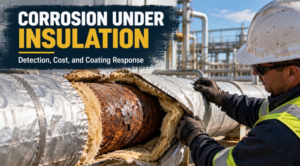
Corrosion Under Insulation: Detection, Cost, and Coating Response
There’s a particular kind of dread that comes with pulling insulation off a pipe that’s supposedly been fine for years and finding the wall thinned down to almost nothing underneath. Corrosion under insulation, usually just called CUI in the industry, earns its reputation as one of the most frustrating asset integrity problems in oil and gas specifically because it happens completely out of sight, often for years, while every visual inspection of the insulated exterior looks perfectly normal.
This piece gets into why CUI happens, why it’s so hard to catch early, what detection actually looks like in practice, and where coating strategy fits into managing a problem that a lot of operators only take seriously after it’s already cost them a shutdown or a near-miss.
Why Insulated Pipe Is Uniquely Vulnerable
Insulation exists to control temperature, keeping hot process lines hot and cold lines cold, and it does that job well. What it also does, almost as a side effect, is create a sealed, dark, often damp environment against the pipe wall that’s close to ideal for corrosion once moisture finds a way in. Rain, wash-down water, condensation from temperature cycling, or a failed vapor barrier can all introduce moisture under an insulation jacket, and once it’s in there, it tends to stay in there, held against the metal surface by the same jacketing that’s supposed to be protecting the pipe.
The temperature range that makes CUI worst isn’t the extremes you’d intuitively expect. Pipe operating consistently very hot tends to stay dry enough underneath that moisture doesn’t linger, and pipe running consistently well below freezing has its own separate set of problems but doesn’t typically see the same corrosion mechanism. It’s the range in between, roughly the band where water can exist as a liquid and cycle between wet and dry, that creates the most persistent corrosion risk. Equipment that cycles between operating and idle, or between different process temperatures, tends to be particularly susceptible, since that cycling actively promotes condensation rather than letting things stay reliably dry or reliably frozen.
Why It’s So Hard to Catch
A visual inspection of insulated piping tells you almost nothing about what’s happening underneath the jacket. The insulation and cladding look fine. The pipe could be fine too, or it could be losing wall thickness at a rate that will lead to a leak within a defined timeframe, and there’s no way to know which from the outside without actually doing something to look underneath or through the insulation.
This is exactly why CUI has a reputation for showing up as a surprise, even at facilities with otherwise solid inspection programs. A piping system might get a thorough external visual inspection every turnaround cycle, checks that catch plenty of real problems on uninsulated equipment, while insulated sections quietly deteriorate underneath jacketing that hasn’t been opened up in years because nothing about it looked concerning from outside.
What Actual Detection Looks Like
A handful of methods have become standard for finding CUI without simply removing every foot of insulation on a facility, which would be prohibitively expensive and disruptive.
Visual inspection with strategic insulation removal remains a baseline approach, focused on areas known to be higher risk, insulation seams, low points where water can collect, areas near penetrations or supports where jacketing is more likely to have failed.
Infrared thermography scans the insulation’s exterior surface for temperature anomalies that can indicate wet insulation underneath, since wet insulation typically has different thermal properties than dry insulation. It’s a useful screening tool for covering large areas relatively quickly, though it doesn’t directly measure corrosion, it flags areas worth a closer look.
Guided wave ultrasonic testing sends a sound wave along a length of pipe and analyzes the return signal for indications of wall loss, allowing inspection of a significant pipe length from a single access point without removing insulation along the entire run. It’s particularly useful for screening long insulated runs to prioritize where more detailed inspection is actually needed.
Real-time radiography and pulsed eddy current testing both allow direct measurement of pipe wall condition through the insulation without removal, each with different tradeoffs in terms of cost, speed, and the specific conditions they work best under.
No single method catches everything reliably on its own, which is why a serious CUI management program typically combines a risk-based approach, focusing detailed inspection resources on the piping most likely to have a problem, with a mix of these detection methods rather than relying on just one.
The Cost Side of the Problem
CUI has a well-documented reputation across the industry as one of the more expensive corrosion mechanisms to manage, not just because of the direct cost of failures when they happen, but because of how much it costs to inspect for proactively across a large facility with miles of insulated piping. Unplanned shutdowns from a CUI-related leak carry costs well beyond the repair itself, lost production, potential environmental or safety consequences, and the kind of reputational damage that follows a preventable failure becoming public.
This cost reality is part of why risk-based inspection approaches have become standard practice rather than trying to inspect every insulated pipe segment on an equal footing. Prioritizing based on known risk factors, operating temperature range, insulation condition, history of moisture ingress, age of the system, gets more value out of limited inspection budgets than a uniform approach would.
Where Coating Strategy Fits
Coating choice matters both for new construction and for CUI mitigation on existing systems, and the goals are somewhat different from typical external pipeline coating decisions covered elsewhere on this site. A coating intended to sit under insulation needs to handle sustained, cyclical moisture exposure in a confined space, along with the specific temperature range the equipment operates in, and ideally provide enough of a barrier that even if moisture does get past the insulation and jacketing, it doesn’t immediately start attacking bare metal.
Surface preparation before applying any CUI-resistant coating matters just as much here as it does for any other pipeline coating application, arguably more, since a coating failure under insulation won’t be visually obvious the way an external coating failure often is. Our guide on properly preparing a pipeline surface before coating covers preparation standards that apply directly to insulated piping systems as much as any exposed application.
It’s worth being clear that cathodic protection, a mainstay of buried pipeline corrosion control, generally doesn’t function the same way for insulated above-ground piping the way it does for buried systems, since CP relies on electrical continuity through the surrounding soil or water that insulated, above-grade piping doesn’t have. Our explainer on how cathodic protection interacts with pipeline coatings covers where CP genuinely applies and where a coating has to carry the corrosion protection burden on its own instead.
Building a CUI Management Program
Facilities that manage this problem well tend to treat it as an ongoing program rather than a one-time coating decision at construction. That means maintaining an accurate inventory of insulated piping with associated risk factors, scheduling risk-based inspection using the detection methods that fit each segment’s risk level and access constraints, and having a clear protocol for what happens once a problem area is found, whether that’s targeted insulation removal for closer inspection, recoating, or in more severe cases, pipe replacement.
Understanding why coatings fail in general terms helps inform what to watch for specifically in a CUI context too. Our root cause analysis of pipeline coating failures covers failure patterns that show up across pipeline coating applications broadly, many of which apply directly to why a coating under insulation might not be performing as expected. For the broader corrosion prevention picture that CUI fits into alongside other mechanisms, our complete guide to pipeline corrosion prevention covers the full toolkit operators draw from, coatings, cathodic protection, soil chemistry, and inspection technology working together rather than any single method carrying the whole burden.
Things to Consider for a CUI Program
- Has the facility’s insulated piping inventory actually been risk-ranked, or is inspection happening on a uniform schedule regardless of actual risk factors?
- Are detection methods matched to each segment’s access constraints and risk level, rather than defaulting to a single method across the whole facility?
- Has coating specification for insulated service actually accounted for the specific moisture and temperature cycling conditions, rather than reusing a standard external pipeline coating spec?
- Is there a documented protocol for what happens once a problem area is identified, so a finding doesn’t sit unaddressed while a decision gets made?
- Are insulation jacketing seals and vapor barriers being inspected and maintained, since preventing moisture ingress in the first place is at least as important as detecting corrosion after it’s already started?
Frequently Asked Questions
What temperature range is most susceptible to corrosion under insulation?
The range where moisture can exist as a liquid and cycle between wet and dry conditions tends to be the most problematic, rather than extreme high or low operating temperatures where conditions stay more consistently dry or frozen.
Can corrosion under insulation be detected without removing the insulation?
Yes, to a significant degree. Infrared thermography, guided wave ultrasonic testing, real-time radiography, and pulsed eddy current testing can all provide useful information without full insulation removal, though targeted removal for direct visual inspection is still often part of a complete program.
Does cathodic protection prevent corrosion under insulation?
Generally not for above-ground insulated piping, since cathodic protection relies on electrical continuity through soil or water that insulated, above-grade systems don’t have. Coating strategy carries more of the corrosion protection responsibility in these applications.
Why is corrosion under insulation considered so costly to manage?
Both the direct cost of failures, including unplanned shutdowns and potential safety or environmental consequences, and the cost of proactive inspection across large facilities with extensive insulated piping contribute to CUI’s reputation as an expensive corrosion mechanism to manage well.
How often should insulated piping be inspected for CUI?
It depends on risk factors specific to each piping segment, operating temperature range, insulation and jacketing condition, moisture exposure history, rather than a single fixed interval applied uniformly across a facility.
Conclusion
Corrosion under insulation is a genuinely difficult problem precisely because it hides so well, and facilities that treat it as an afterthought behind more visible corrosion concerns tend to find out the hard way that it doesn’t stay hidden forever. Building a real risk-based inspection program, choosing coating systems actually suited to the moisture and temperature conditions under insulation rather than reusing a standard external spec, and maintaining the insulation jacketing itself to keep moisture out in the first place are what separate facilities that manage this problem proactively from ones that discover it during an unplanned shutdown.